I. The Core Conclusion: The "Three Axes" of Qualification
To determine if a BGA Rework is truly "qualified," relying solely on the device powering up is dangerous. A successful boot only proves the current logic state; it does not guarantee reliability against thermal cycling, vibration, or long-term operation. True qualification requires passing three simultaneous checks—Visual, Structural (X-Ray), and Electrical—strictly adhering to IPC-7095 (Design and Assembly Process Implementation for BGAs) and IPC-A-610 (Acceptability of Electronic Assemblies) standards.
II. Deep Dive: The Three Dimensions of Acceptance
1. Visual Inspection & Installation Attitude
Standard Basis: IPC-A-610 Class 2/3
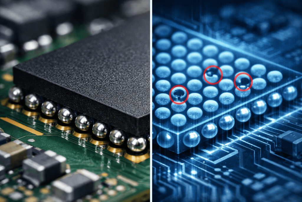
Although the primary BGA solder joints are hidden beneath the component body, a peripheral inspection is the first line of defense against process flaws.
-
Inspection Focus: Must use a stereo microscope or an oblique angle camera inspection system (never naked eye).
-
Key Indicators:
-
Polarity & Orientation: Must match the silkscreen or Pin 1 indicator perfectly.
-
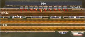
Coplanarity & Collapse: Observe the solder ball collapse around the perimeter. Uneven collapse often signals the dreaded Head-in-Pillow (HiP) defect or potential open circuits.
-
Contamination: Ensure no flux residue (unless using No-Clean process) and absolutely no visible external solder bridging.
-
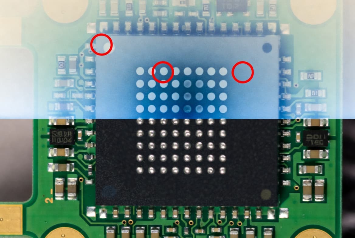
2. Structural Integrity (X-Ray / 5DX Inspection)
Standard Basis: IPC-7095D
This is the "Gold Standard" for BGA qualification. Since optical inspection cannot reach the inner array, X-Ray penetration is mandatory.
-
Voiding Rates — 25% is the Red Line
-
Industry Data: According to IPC-7095 and multiple reliability studies, the void area of a single solder ball must not exceed 25% of the ball's cross-sectional area.
-
Risk Warning: Research indicates that when voiding exceeds 25%-35%, cracks tend to propagate along the void interface, causing solder joint life to drop exponentially. For Class 3 High-Reliability products, many OEMs strictly cap this at 15%-20%.
-
-
Alignment (Offset)
- Quantifiable Metric: Under X-Ray, the offset between the solder ball center and the pad center should not exceed 25% of the ball diameter (Strict Process) to 50% (IPC-A-610 Class 2 limit).
-
Bridging (Shorts)
- Zero Tolerance: Any form of solder bridging between joints is a critical failure requiring immediate rework.
3. Electrical & Functional Verification
Strategy: Logical verification after physical confirmation.
-
Test Sequence: It is highly recommended to perform X-Ray verification before powering on. Powering a shorted BGA can permanently damage the PCB or the silicon.
-
Test Depth:
-
Basic: Resistance-to-ground test (Multimeter/Flying Probe) to ensure no power rail shorts.
-
Advanced: Boundary Scan (JTAG). This technology can verify the connectivity of every BGA pin (including redundant power or unused I/Os) which a simple "boot test" will miss.
-
III. Watch Out! Three Common Industry Myths (2024-2025)
After consulting with senior SMT engineers and reviewing recent technical reports, we have identified these high-frequency misconceptions:
Myth 1: "It Powers On, So It's Good"
-
The Reality: "Powering on" only validates that critical power and data lines are connected at this moment.
-
Industry Insight: Technical analysis from Millennium Circuits Limited points out that simple functional tests cannot detect "latent defects" like excessive voiding or "bonepile" weak contacts. These defects pass initially but fail after field thermal cycling.
Myth 2: A Naked Eye Glance Counts as "Visual Inspection"
-
The Reality: BGA solder joints are obstructed; human vision covers less than 10% of the risk area.
-
Industry Insight: Manufacturing guides from Suntronic Inc. emphasize that for high-density PCBs, visual checking without magnification is negligible. Optical inspection (AOI) or high-mag scopes must be used to check the outer rows for "cold solder" signs before X-Ray.
Myth 3: "The X-Ray Looks 'About Right'" is Acceptable
-
The Reality: Subjective operator interpretation is the biggest killer of quality control.
-
Industry Insight: Recent articles from AllPCB and Viscom suggest that relying on an operator's "feeling" is obsolete. Modern lines must use Automated X-Ray Inspection (AXI) with software that calculates "Void %" and "Ball Circularity." If you can't quantify it, you can't pass it.
If you build your process around these principles—visual, structural, and electrical checks backed by clear written criteria—you’ll stop asking, “Is power-on enough?” and start asking the better question: “Does this BGA rework meet our defined reliability standard?”