Completely solving the problem of "unreliable low-end BGA rework equipment": The ultimate engineering-grade tutorial.
In the field of BGA rework, almost every engineer and repair technician has asked the same question at some point: "Why, even though I followed the procedure exactly, does the board get worse each time?" This article is not meant to "motivate" beginners, nor is it an equipment advertisement. It only addresses one question: Why are low-end BGA equipment destined to fail at a physical level? And how to solve this systematically.
Part One | The Problem: Low-end equipment is creating "uncontrollable rework"
Common failure scenarios
- Reflow seems successful at the time, but fails after 24–72 hours. The typical symptom is that the device functions normally when it comes off the line, but after several cycles of thermal cycling or 24–72 hours of rest, the BGA solder joints experience intermittent disconnections, which eventually become apparent in high-load applications such as graphics cards, motherboards, and servers. For the failure mechanism of BGA solder joints under thermal cycling conditions, please refer to materials such as "BGA Solder Joint Detection Technology and Quality Control," which provides a systematic explanation of solder joint fatigue caused by thermal cycling.
- Some chips of the same model can be repaired, while others inevitably fail. This "mysterious" phenomenon is extremely common on low-end rework stations that only have single-point heating and no whole-board preheating function: local areas are repeatedly overheated, while the average temperature of the entire board is too low, resulting in excessive thermal stress concentration, leading to chip warping, solder ball cracking, and cracks. You can compare this to the three-stage heating structure of professional rework stations (upper hot air + bottom preheating + large-area infrared/hot air zone) to understand the differences in thermal field distribution.
-
Pad detachment and chip displacement without finding the cause. Many workshops mistakenly attribute these problems to "poor board quality" or "poorly made pads," but from the perspective of equipment principles, the greater variable often comes from excessively steep temperature gradients, unstable mechanical alignment, and Z-axis movement, resulting in shear force or impact force at the moment of solder melting. Key judgment: If your rework results "highly depend on luck," then the problem is definitely not in your personal skills, but rather that the physical boundaries of the equipment and process are out of control.
Part Two | The Root Cause: 3 Structural Defects of Low-End Equipment
Root Cause 1: Open-loop Heating
Single-point temperature measurement ≠ solder joint temperature
Many entry-level BGA rework stations only have a closed-loop temperature control for the heating head, or even just a "hot air outlet temperature display," without multi-point, real-time temperature measurement of the PCB and solder joints themselves. However, what needs to be controlled in engineering is the temperature trajectory of the solder joint layer, the bottom of the chip, and different areas of the PCB, not "how hot the hot air outlet is."
- References:
BGA Rework Station Working Principle and Upper and Lower Heating Structure Analysis
BGA Rework Station Structure and Temperature Control Method Description
Center and Corner ΔT often exceeds 30–50°C
Without a large-area preheating plate and multi-zone temperature control, the temperature difference between the center and corners of a BGA on a large-sized PCB (server boards, graphics cards, large industrial control boards) easily exceeds 30–50°C. The larger the temperature difference, the more uneven the thermal stress on the solder joints, and the worse the self-centering effect at the moment of melting, ultimately resulting in localized cold solder joints, eccentric voids, and stress concentration cracking.
📊 Engineering Data (Illustrative Empirical Range)
When BGA solder joint ΔT > 25°C: The probability of cold solder joints/false soldering can increase to several times that of "under normal process conditions." In actual profiling and X-ray statistics from many factories, a sharp increase in defects in the center or diagonal solder joints was observed in scenarios with large temperature differences. Although the specific multiplier varies for different products and solder systems, the trend of "excessive ΔT → significant increase in defects" is highly consistent in a large number of engineering cases and process specifications.
Root Cause 2: Displayed Temperature ≠ Actual PCB Temperature
Low-end equipment only measures the heating head; the actual solder joint temperature is "guessed"
The "temperature curve" of many low-end BGA rework stations is essentially just feedback on the heater or hot air outlet, not the actual temperature of the PCB/BGA solder joint layer. The standard practice should be to attach thermocouples to the PCB to establish a true temperature profile, and then use the device's heating power to "track" this profile.
📊 Measured Results (Common Engineering Findings)
In numerous field measurements, the following data is frequently observed: The device displays a temperature rise to 235°C; The actual solder joint temperature (measured with a thermocouple attached to the edge or center of the BGA) is only 205–210°C. For lead-free solder systems, this means: The solder has not fully reached the recommended reflow peak temperature range and dwell time; Insufficient solder wetting, solder not flowing into the vias, and unstable intermetallic compound layers at the interface, leading to the classic scenario of "it works now, but fails in a few days."
Root Cause Three: "Human Error" Caused by Insufficient Mechanical Precision
Z-axis wobble, manual alignment is not reproducible
To control costs, low-end equipment often makes significant compromises on critical mechanical modules:
- Insufficient rigidity of the Z-axis guide rails and slider precision leads to unstable vertical movement, resulting in slight impacts or displacement at the moment of solder melting.
- X/Y alignment relies on manual measurement with rulers and visual adjustment with a magnifying glass, lacking optical alignment and repeatable positioning benchmarks. In contrast, professional-grade BGA rework systems typically feature:
- Linear guides and precision ball screws for controllable and reproducible Z-axis lowering/lifting;
- Optical alignment system (upper and lower image overlay), supporting alignment accuracy of 0.01–0.02mm;
- Vacuum suction nozzle and controlled descent to avoid impact when the solder is just melting.
- Example device characteristics can be found in:
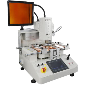
- Introduction to a three-zone upper and lower hot air + bottom infrared, automatic pick-and-place and soldering rework system.
- High-end rework systems that use non-contact infrared temperature sensors to achieve closed-loop temperature control and ensure uniform heat distribution.
📊 Comparative Data (Typical Trends)
In systems with alignment accuracy ≤ 0.02mm: The first-pass rework success rate can be improved by approximately 20–30 percentage points compared to the traditional "manual alignment + manual pressing" method; Problems such as chip offset, warping, and bridging are significantly reduced, especially noticeable on high-density BGAs with a pitch of 0.5mm or less.
Part Three | Solution: Engineering Level, Not "Equipment Upgrade" Level
Important Statement: This is not a recommendation to "buy the most expensive equipment," but a recommendation to "fill the minimum engineering capabilities"—replacing luck with engineering closed-loop control.
Solution One: Three-Stage True Closed-Loop Heating System
A qualified BGA rework heating architecture should at least simultaneously possess:
- Upper Hot Air (Controllable Airflow)
- Replaceable nozzles, independently adjustable airflow and temperature, supporting airflow optimization for different package sizes.
- Reference: For an explanation of the working principle of the upper hot air head and nozzle combination, please refer to the professional rework station working principle article.
- Bottom Board Preheating
- Large-area infrared or hot air preheating zone to slowly heat the entire board, reducing thermal shock shock and board warping.
- For example: Rework equipment with a three-temperature zone structure (upper and lower hot air + bottom infrared) achieves a more uniform temperature distribution through independent zone heating.
- PCB Solder Joint Level Temperature Feedback
- Supports external thermocouples and curve recording, rather than just looking at the "displayed temperature";
-
High-end systems even use non-contact infrared temperature sensors to measure the BGA surface temperature in real time and achieve closed-loop control. Only the combination of these three can be called a "closed-loop thermal field," otherwise, it's just a "heating tool."
Solution Two: Process Curve Templating
Core Principle
BGA rework is process engineering, not "manual art." All experience should ultimately be distilled into repeatable temperature curve templates, not the intuition of a particular technician.
Minimum Requirements
In lead-free BGA rework scenarios, a qualified curve should at least include:
- Ramp / Soak / Reflow segments
- Ramp: Controls the heating rate to avoid board warping and solder cracking due to excessive ΔT.
- Soak: A constant temperature zone for a certain period of time, used to equalize the temperature across the entire board and activate the solder pads and solder surface.
- Reflow: Reaching the peak temperature and maintaining it for an appropriate time to ensure complete melting and wetting of the solder.
- Lead-free Curve Template
- For SAC series lead-free solder, the peak temperature is usually higher than that of eutectic tin, requiring a more rigorous temperature control window.
- Relevant suggestions can be found in the typical curve ranges given in the SMT/BGA Rework Process Guide.
- Adjustable Soak Time (90–150s)
- For large-mass PCBs or thick copper boards, a longer soak time is required to ensure that the inner and outer layer temperatures are close;
-
Make parameters such as soak time, peak temperature, and reflow time into selectable templates, and call them according to the board type, instead of "re-sensing" them every time.
Solution Three: Upgrading "Equipment" to a "System"
A qualified BGA rework system should include at least the following elements:
- Stable Rework Platform
- With a rigid support, adjustable clamps, and a support structure suitable for large boards;
- Smooth X/Y/Z movement and high repeat positioning accuracy to avoid micro-vibrations during operation that could impact the solder joints.
- Vacuum Pickup + Slow Descent Mechanism
- Automatically picks up components, avoiding manual manipulation with tweezers;
- Provides controllable downward/upward speed during the solder melting and cooling phases to reduce mechanical stress impact.
- Dedicated Flux/Stencil/Nozzle
- Different nozzles, stencils, and fixtures are matched for different sizes and pitches of BGAs;
- Use low-residue flux optimized for BGA rework, combined with precise solder removal and reballing processes. In summary:
- Single-machine thinking = Uncontrollable (equipment is just "heating + air")
-
System thinking = Reproducible profitability (equipment + process + tooling + data feedback loop)
Part Four | Real Case Study: The Turning Point of a Graphics Card Repair Workshop
Starting Point: "Mystical Repair" with Low-End Equipment
- Scenario:
- A graphics card repair workshop mainly handles high-power GPU devices such as gaming graphics cards and mining cards.
- The initial setup consisted of an entry-level BGA rework station and a handheld hot air gun, lacking full board preheating, temperature profile recording, and optical alignment systems.
- Data Performance:
- Original success rate: ≈ 55% (based on the standard of "normal operation for 7 days");
- Customer complaints were concentrated on failures after 48 hours: manifested as screen flickering, black screen, intermittent crashes, etc.
Upgrade Actions: From "Equipment" to "System"
- Introduction of a three-stage closed-loop rework platform
- Using a BGA rework system with upper and lower hot air + bottom preheating + multi-zone temperature control structure;
- Using thermocouples to establish a standard lead-free reflow profile on typical graphics cards, controlling ΔT within a reasonable range.
- Template-based Process and Standard Tooling
- Establishing fixed nozzle schemes, support fixtures, and stencil configurations for mainstream GPU packages;
- Solidifying Ramp/Soak/Reflow parameters in the equipment program, allowing new engineers to simply call up the parameters according to the work order.
- From "Master's Intuition" to "Data Monitoring"
- Recording data for each reworked board, including profile, first-time success rate, and number of reflow cycles;
- Evaluating the rework performance of different GPU models and board types over a 30-day period, continuously fine-tuning the curves.
Results (30-day period)
- First-time success rate: increased from ≈ 55% to ≈ 92%;
- Second rework rate: decreased by approximately 67% (many boards that previously required "more than two reworks" were completed in one attempt);
-
The proportion of "failures within 48 hours" in customer complaints was significantly reduced, and long-term repeat customers and referrals increased significantly.
Conclusion: The real risk is not the equipment, but "misjudgment"
The biggest danger of low-end BGA rework equipment is not "failure to repair," but: It leads engineers to misjudge the cause of failure——— Mistaking physical-level issues such as uncontrolled thermal fields, insufficient mechanical precision, and lack of closed-loop temperature measurement for "lack of technical skill" or "the chip being too difficult to repair."