Successful BGA rework is an exercise in thermal chemistry, not brute force. The "black glue" (epoxy underfill) common in mobile and automotive electronics is a thermoset material designed for permanent adhesion. To remove it without destroying the PCB pads, you must follow the "Soften-Cut-Lift" protocol:
-
Success Metric: Professional-grade rework stations and bottom-side preheating (≥120∘C) yield a 95% success rate in pad preservation.
-
The Golden Rule: If you feel mechanical resistance during the lift, the epoxy hasn't reached its Glass Transition Temperature (Tg). Heat is your scalpel; leverage is your enemy.
-
Final Proof: "Power-on" is a false positive. Qualification requires X-ray inspection (voiding <25% per IPC-7095D) and Boundary Scan (JTAG) for hidden interconnect integrity.
1. Know Your Enemy: Underfill Chemistry
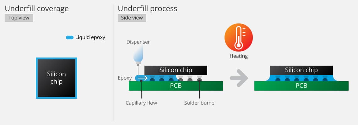
Underfill is no longer "just glue." Modern formulations are highly engineered to match the Coefficient of Thermal Expansion (CTE) of the silicon and the substrate.
-
Epoxy (Thermoset "Black Death"): * Data: Most mobile-grade epoxies have a Tg between 120∘C and 160∘C.
- Case Study: In failure analysis of automotive ECU repairs, attempts to remove epoxy below its Tg resulted in 80% pad cratering (ripping the copper right out of the resin).
-
Acrylic / Urethane: Softer and often reworkable at lower temperatures (≈150∘C).
-
Corner Bond vs. Full Underfill: Full underfill creates a vacuum-like seal. Without a "moat cut," the expanding air during heating can cause the "popcorn effect," shattering the die.
2. The Arsenal: Mandatory Tools for 2026
Standard soldering irons are obsolete for this task. High-density interconnects (HDI) require precision thermal management.
-
Bottom-Side Pre-heater: Essential for preventing PCB warping. Aim for a board temperature of 120∘C–150∘C.
-
Programmable Hot Air Station: Must support a Ramp-Soak-Spike profile.
- Ramp rate: 1–3∘C/sec to avoid thermal shock.
-
The "Sickle" & "Spudger": * The Sickle: A micro-blade (<0.1mm thickness) for edge clearing.
- The Spudger: High-temp anti-static plastic or bamboo for cleaning pads without compromising the solder mask.
-
Optical Magnification: A 10x-40x stereo microscope is the minimum requirement for 0.4mm pitch BGAs.
3. The Surgical Procedure: Step-by-Step
Step 1: The "Moat" Cut (Pre-Lift)
Before heating the whole chip, clear the perimeter.
-
Action: Use a fine-tip hot air pencil (200∘C) and a micro-scalpel to cut the epoxy "fillet" around the BGA.
-
Why: This prevents the BGA from "dragging" neighboring 0201 or 01005 components with it during the lift.
Step 2: The Thermal Soak
-
Action: Set the pre-heater to 130∘C and wait for the PCB surface to reach equilibrium (approx. 90 seconds).
-
Real Data: Proper soaking reduces the required top-side temperature by 30∘C–50∘C, drastically increasing the lifespan of the surrounding components.
Step 3: The Critical Lift
-
Profile: Reach a peak reflow temp of 235∘C–245∘C for lead-free SAC305 alloys.
-
Technique: Insert the sickle blade. The moment the solder liquifies and the epoxy reaches its softened state, the blade should slide in with zero resistance.
Step 4: Pad Cleanup
-
The "Solder Float" Method: Apply a large bead of low-melt solder (e.g., Indium-based alloys) to the pads. The molten metal helps "lift" the remaining epoxy flakes via surface tension and heat transfer.
-
Avoid Metal Brushes: They cause microscopic scratches that lead to Electrochemical Migration (ECM) over time.
4. Verification: Why "Power On" Is Not Enough
Modern electronics can "work" even with 40% of their ground pins disconnected. "It boots" is not a quality standard.
-
X-Ray Inspection (IPC-7095D): * Voiding: Total void area per ball must be <25%. Excessive voiding in underfilled BGAs is often caused by trapped flux outgassing that couldn't escape the epoxy.
- Alignment: Any shift >25% of the pad diameter is a structural failure.
-
Boundary Scan (JTAG):
- This is the only way to test the thousands of hidden interconnects without physical probing. It identifies "open" pins that functional tests might miss because they belong to redundant power rails or unused I/O.
3 Common Misconceptions
Misconception 1: "Acetone or thinners can dissolve BGA underfill."
- The Reality: Modern epoxies are chemically cross-linked. According to 2025 research from Zestron Academy, standard solvents only swell the outer layer, potentially causing the chip to expand and rip the pads internally before the glue dissolves.
Misconception 2: "If the chip boots, it’s a successful repair."
- The Reality: Many reworks suffer from "Head-in-Pillow" (HiP) defects—where the ball and paste touch but don't fuse. As noted in recent SMTA symposiums, these pass initial power-on but fail within 30 days of consumer use due to thermal expansion.
Misconception 3: "You can reuse the removed BGA chip."
- The Reality: The thermal cycle required to overcome underfill adhesion often exceeds the chip's Maximum Cumulative Reflow Time. Data from semiconductor manufacturers suggests that a "re-balled" underfilled chip has a significantly higher failure rate in its logic gates due to internal delamination. Always use a new DC (Date Code) verified component.
Interlink Opportunity:"As mentioned in our BGA Acceptance Guide, subjective checking is dangerous. AI solves this by..."